
WILL NEED TO CREATE A UNIQUE MENU FOR THIS PAGE ONLY!!!
Use these resources to integrate a Lift Shop lift into your plans quickly. All drawings are indicative and for design coordination only. Final shop drawings and certificates are issued once the project is confirmed.
Indicative data for early design. Confirm final numbers with our technical team before construction.All dimensions indicative only. Site conditions, door choices and travel height can alter requirements.
| A Series - Italian | C Series - Italian | E Series - Italian | |
|---|---|---|---|
| Lead Time - Custom - 6 months *Stock and labour availability vary | ✓ | ✓ | ✓ |
| Speeds | 0.30 m/s 10 secs/floor | 0.30 m/s 10 secs/floor | up to 0.60 m/s 5 secs/floor |
| Capacity | 4 - 6 persons | 4 persons | up to 7 Persons |
Included: In Cabin Self Rescue | ✓ | ✓ | ✓ |
| Included: 1 month free storage | ✓ | ✓ | ✓ |
| Included: Scaffold for lift installation | ✓ | ✓ | ✓ |
| Included: GSM unit | ✓ | ✓ | ✓ |
Up to 6 floors | ✓ | ✓ | ✓ |
Cabin Sizes | ✓ | ✓ | ✓ |
Pit & Headroom Requirements | Pit Depth: 150mm Headroom: 2400mm-2600mm | Pit Depth: 190mm Headroom: 2550-2700mm | Pit Depth: 270mm Headroom: 2750mm |
Power Requirements: Single Phase | ✓ | ✓ | ✓ |
| Drive | Electric Hydraulic | Geared Electric | Gearless Electric |
Machinery Location | Small Cabinet Near lift | Small Cabinet 840 x 600 x 300mm | Machine Room Less |
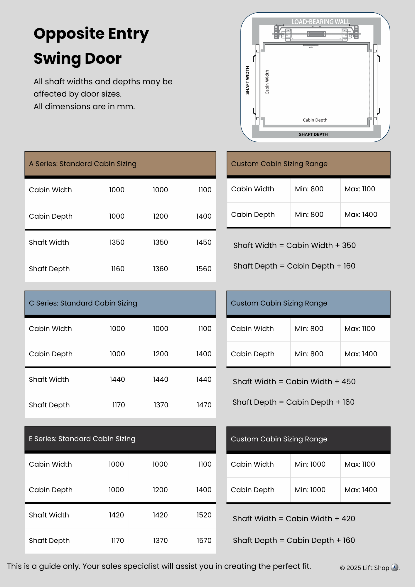
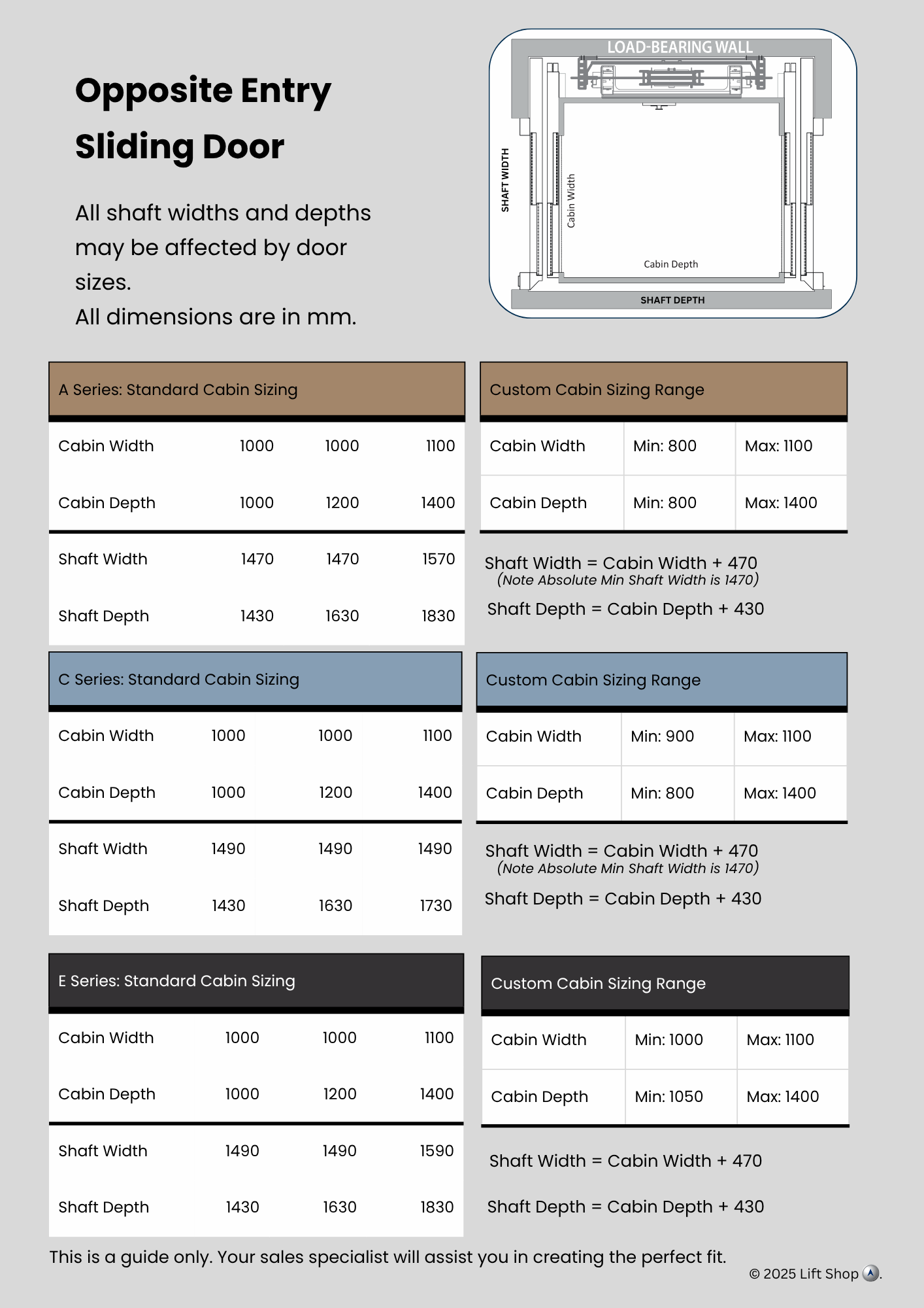
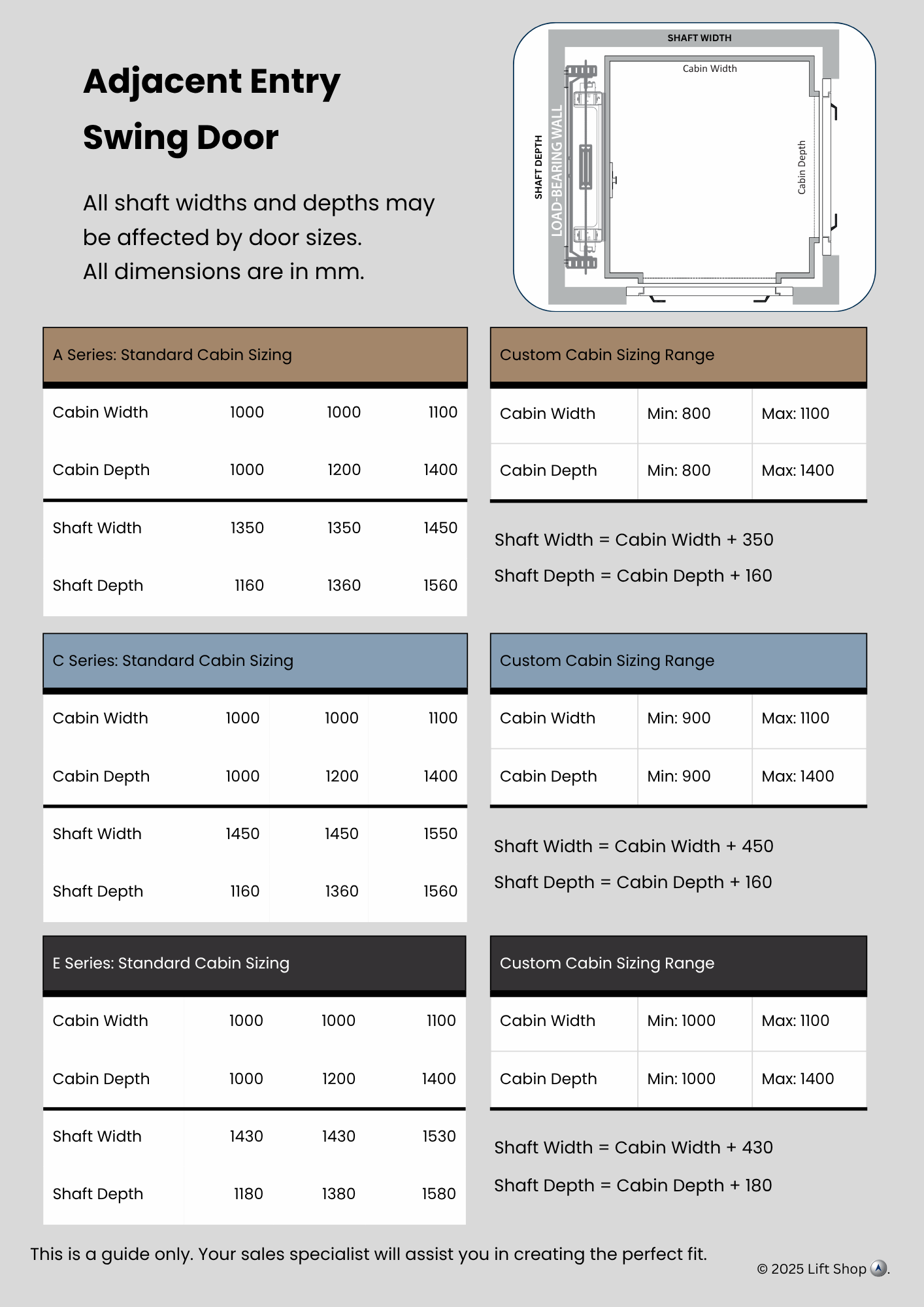
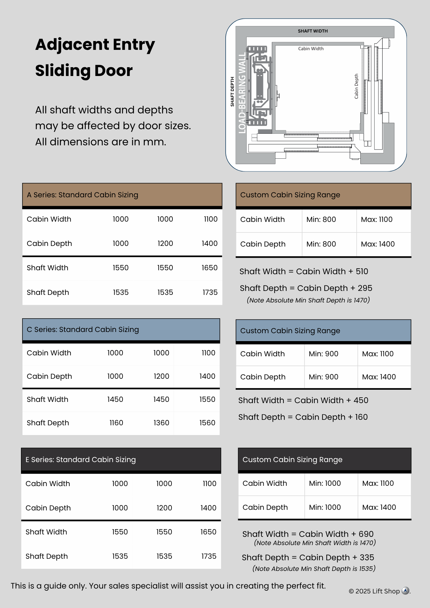
This guide helps you allow for structure, services and finishes during design development.
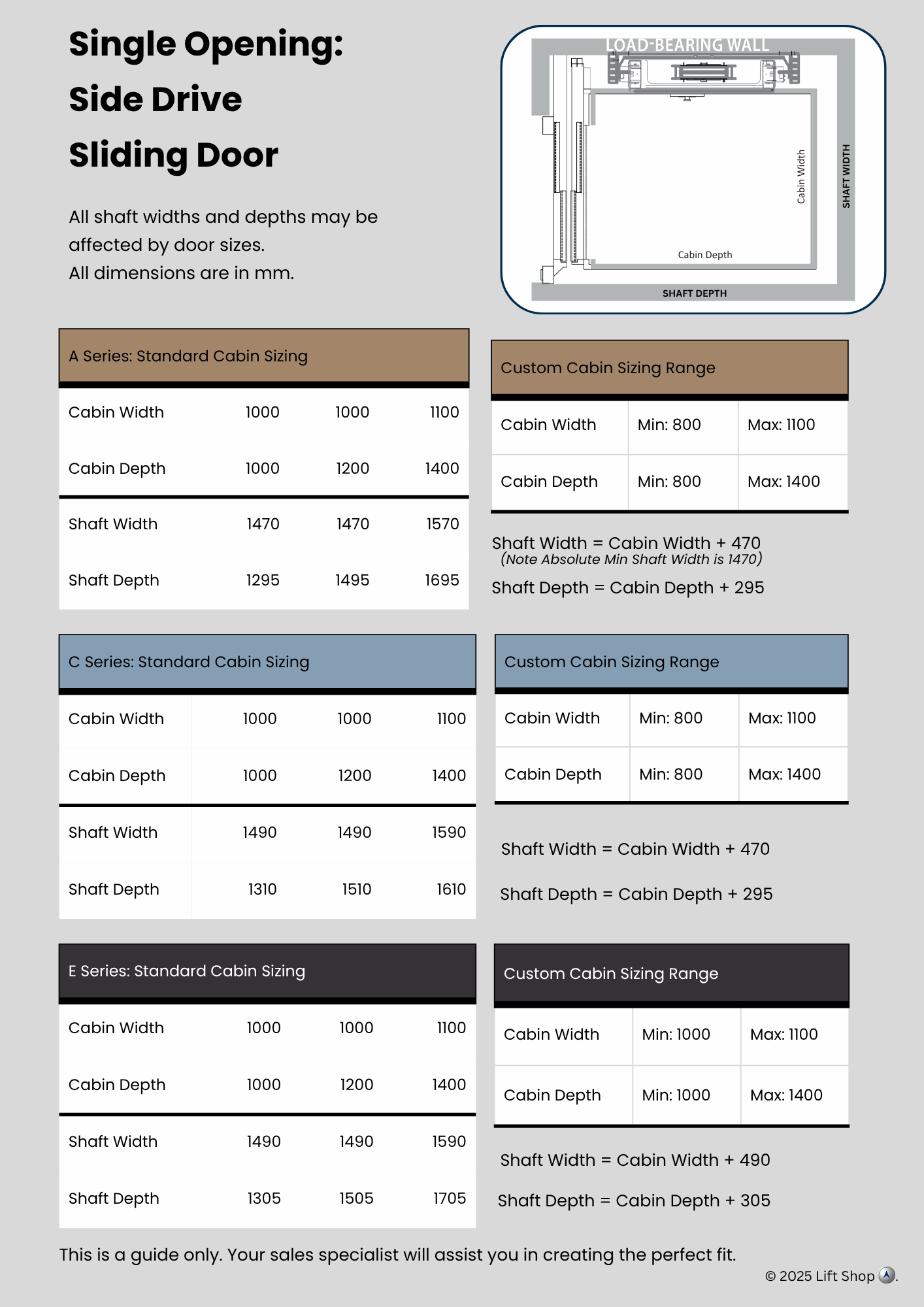
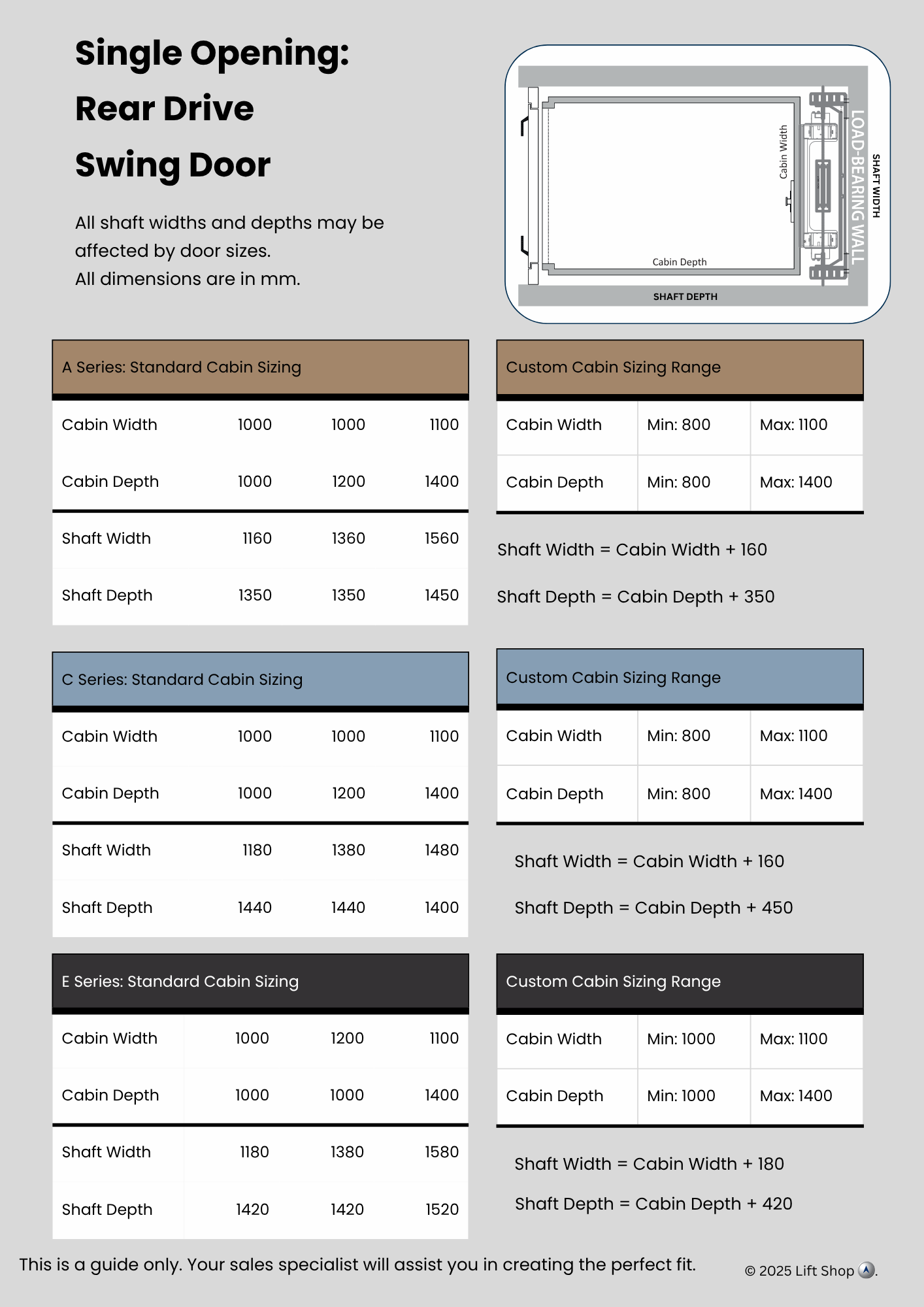
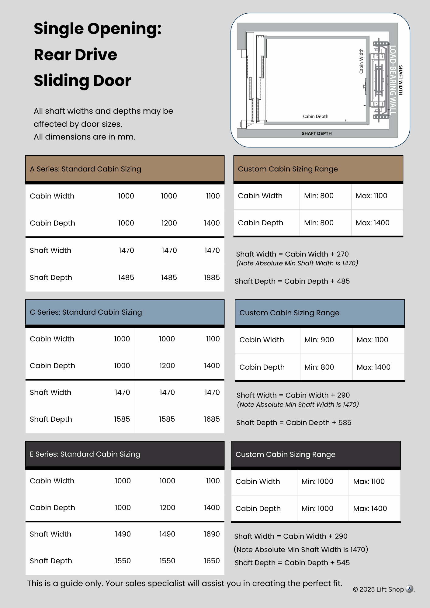
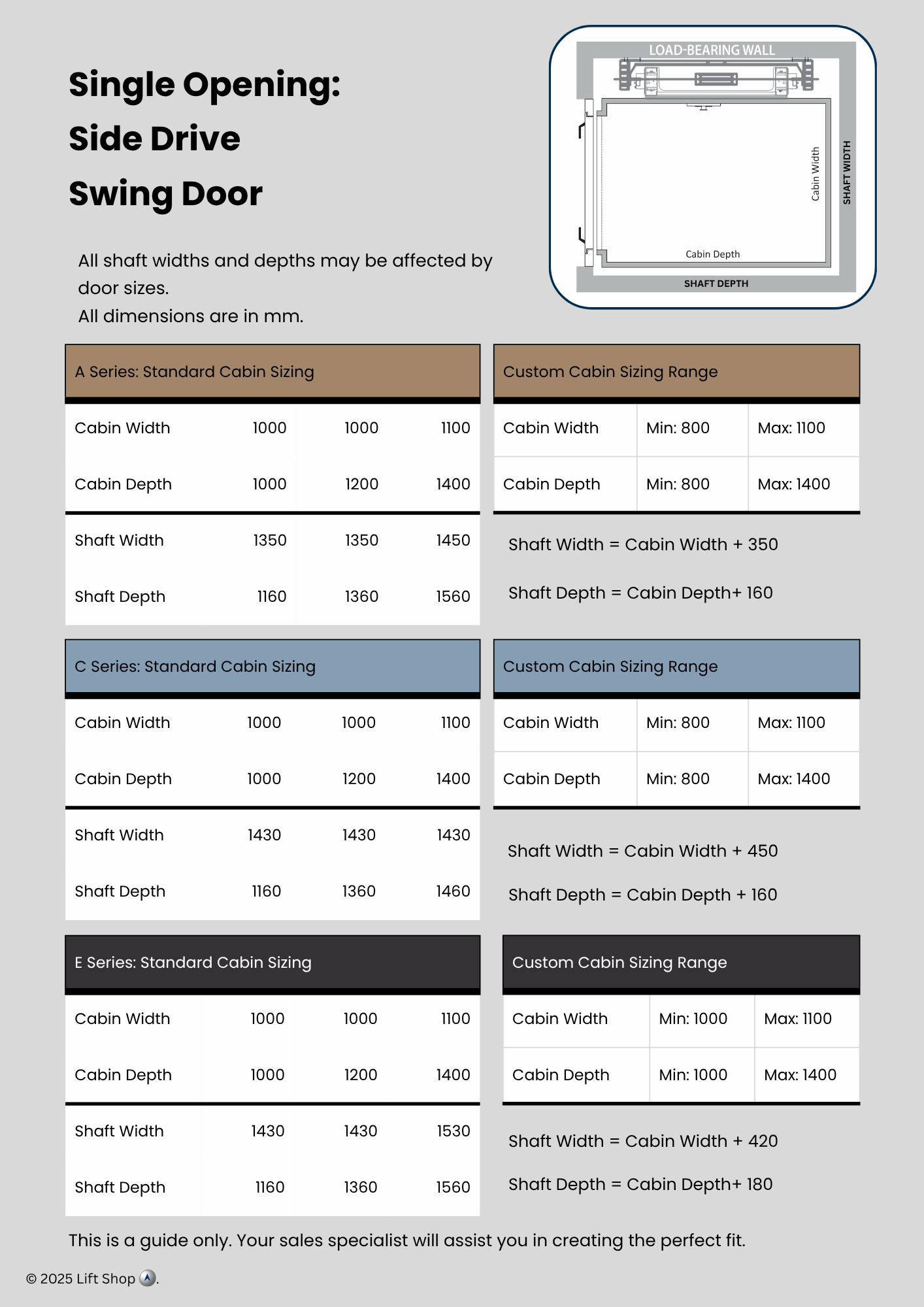
Click on the image below for the indicative sizing for Cabin Width, Cabin Depth, Shaft Width and Shaft Depth.
| A Series | C Series | E Series | |
|---|---|---|---|
| Lift Pit | 150 mm | 150 mm | 270 mm |
| Headroom | 2600 mm | 2550 mm | 2600 mm |
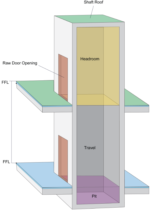
To note:
Headroom is located at the top of the lift shaft and is required for installation. If additional headroom is available, extra travel tolerance can be achieved.
The finished floor level (FFL) is provided by the client before the lift goes into production. Lift Shop requires a signed Final Drawing and Design, including FFL confirmation, before manufacturing begins. This documentation will be issued by your sales representative once a signed contract and initial deposit are received.
This list can be passed onto your electrician to ensure that all electrical elements within the shaft are set up correctly for installation.
Please consult your Sales Assistant if you have any questions.
Note: These are standard requirements; however, there may be slight variations for your lift model.
| Electrical Requirement | Location |
|---|---|
| 1. 32A (Hydraulic), 25A (Electric) Single Phase Power Supply | Next to the Controller |
| 2. 1 × Single Power Point (GPO) to Machine Area | Next to the Controller |
| 3. 1 × Single Power Point (GPO) for GSM Phone Line | 250 mm from the Isolator |
| 4. Lockable 3-Pole Isolator | Readily accessible next to the Controller |
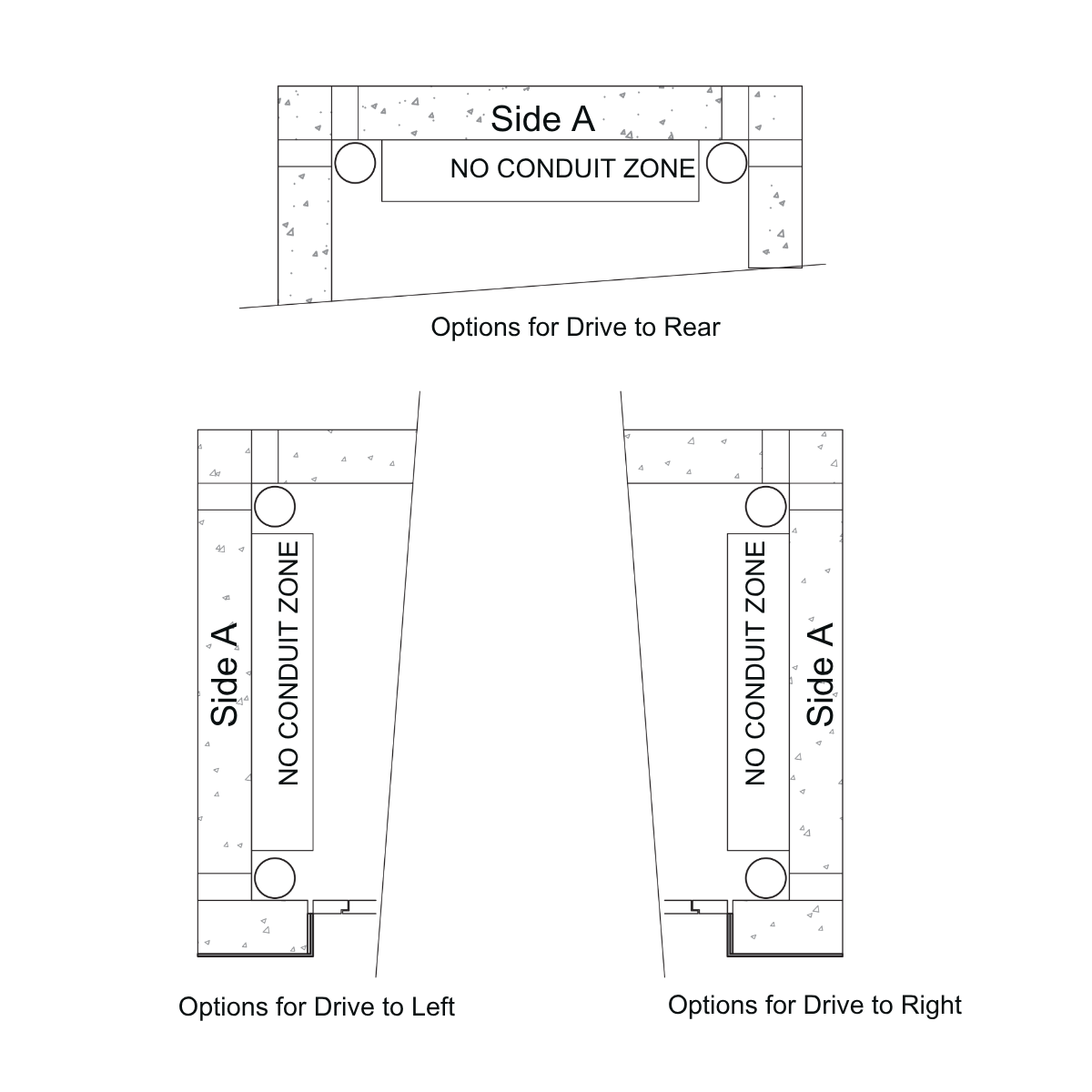
| 5. Conduit in slab or core hole to remote Machine Area or next to Shaft. Differs based on project. See individual series pages for details. | From the Shaft → Machine Area |
| 6. E Series Lift Only: An additional 2 × 2.5 mm SDI | From Isolator to the top of the Controller Cabinet + 3 m tail |

(Client Responsibilities)
a) Lift controller to be positioned back-to-back with the lift shaft in a readily accessible location.
b) A cable entry opening is required between the lift controller cabinet and the lift shaft. The size and height of this opening will depend on the selected lift model.
c) Fixing points to be provided in the wall where the lift controller cabinet is to be mounted, either by noggins or plywood before plaster.
d) For electric traction lifts, provide a dedicated single-phase (240V), 25-amp supply to the lift control cabinet area with an isolation switch mounted adjacent to the cabinet.
e) Lift mains are to be terminated to a lockable 3-pole isolator.
f) Isolator to be present with supply terminated and live for commissioning. During installation, a temporary supply terminated into the isolator will be sufficient.
g) Fire-rated mains are only required if specified by an architect or consultant.
h) Provide lighting, emergency lighting, and general-purpose power to the lift control cabinet area.
i) Provide clear standing room in front of the lift control cabinet as required by applicable standards.
j) Lift machine area must be clean, dry, and free from humidity.
k) In the case of an emergency, 24-hour access to the controller is required. Provide an illuminated clear pathway to the controller (minimum 450 mm width, 2000 mm height).
This specification outlines the standard electrical and mounting provisions required for electric traction lifts. Model-specific dimensions, connection points, and isolation switch heights must be confirmed using the manufacturer’s lift submittal drawings and final approved shop drawings before installation.

Cabins can be specified to match residential interiors or boutique commercial spaces.
Matte White, Brushed Stainless, Brushed Bronze, Polished Stainless, custom powder coat.
Swing or sliding, with glass or solid panels. Auto operation available.
Vinyl options, stone/tile up to 20 mm, or client-supplied floor.
LED downlights, feature ceilings, perimeter glow lighting.
Lift Shop lifts are designed to align with Australian standards and building codes so you can specify with confidence.
Project-specific compliance documentation is issued with the final approved lift package.
Allow for the following during design so installation can proceed without delays.
A and C Series: 150 mm. E Series: 270 mm. Provide drainage or waterproofing where required.
Allow 2550–2750 mm at the top level, depending on model and door type.
Dedicated circuit, isolation within 1.5 m of the control equipment, and space to access the cabinet (min. 600 mm clear).
Control cabinets are compact and quiet (<55 dB typical). Plan for future service access.
Lift Shop systems are built for long service life and efficient operation.